RVT_ELEC_01101 Latest Real Exam, RVT_ELEC_01101 Exam Exercise
Wiki Article
2026 Latest DumpsFree RVT_ELEC_01101 PDF Dumps and RVT_ELEC_01101 Exam Engine Free Share: https://drive.google.com/open?id=19wNaJWtuLyUvrDdGyvvd3HX91OLDzc3k
In the era of rapid changes in the knowledge economy, do you worry that you will be left behind? Let's start by passing the RVT_ELEC_01101 exam. Getting a RVT_ELEC_01101 certificate is something that many people dream about and it will also bring you extra knowledge and economic benefits. The RVT_ELEC_01101 latest question we provide all candidates that that is compiled by experts who have good knowledge of exam, and they are very experience in compile study materials. Not only that, our team checks the update every day, in order to keep the latest information of RVT_ELEC_01101 Exam Question.
Autodesk RVT_ELEC_01101 Exam Syllabus Topics:
| Topic | Details |
|---|---|
| Topic 1 |
|
| Topic 2 |
|
| Topic 3 |
|
| Topic 4 |
|
| Topic 5 |
|
>> RVT_ELEC_01101 Latest Real Exam <<
Autodesk RVT_ELEC_01101 PDF Questions [2026] To Gain Brilliant Result
Do you want to pass the RVT_ELEC_01101 exam by the first attempt? Our RVT_ELEC_01101 exam questons can be our best assistant on your way to success. And the pass rate of our RVT_ELEC_01101 study guide is high as 98% to 100%, which also prove our excellent quality. If you study with our RVT_ELEC_01101 praparation guide, they will strengthen your learning skilles, add to your knowledge and will enable you to revise the entire syllabus more than once. And you will pass for sure with our RVT_ELEC_01101 learning quiz.
Autodesk Certified Professional in Revit for Electrical Design Sample Questions (Q63-Q68):
NEW QUESTION # 63
Refer to exhibit.
A portion of an electrical fixture family's Type Properties is shown in the exhibit.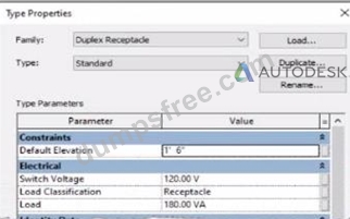
Because of the value of the Type Parameter Load Classification, an electrical designer expects the fixture's Load Classification to display as -Receptacle" when circuited. Instead, it displays as "Other".
What should the designer do to make the circuited fixture's Load Classification always match the family's Type Parameter?
- A. Edit the family. Change the power connector's Load Classification to "Receptacle". Reload the family into the project.
- B. Edit the family. Delete the power connector and place a new power connector. Parameter associations will be made automatically. Reload the family into the project.
- C. Edit the family. Associate the power connector's Load Classification with the family parameter. Reload the family into the project.
- D. Edit the fixture Instance in the System Browser. In the Load Classification column, associate the fixture's Load Classification to the family parameter.
Answer: C
Explanation:
In Autodesk Revit Electrical Design, each electrical family (such as a receptacle, lighting fixture, or equipment) can contain one or more connectors that define how it interacts with the electrical system. The Load Classification parameter determines how the connected load is categorized in electrical schedules and load calculations (e.g., Lighting, Power, Receptacle, Other).
When a family's Type Parameter Load Classification does not display correctly (e.g., it shows "Other" instead of "Receptacle" after being circuited), the issue lies in the power connector's internal parameter not being linked to the family-level "Load Classification" parameter. Revit uses the connector's classification to determine the load type when it is connected to a circuit - if the connector isn't associated, the classification defaults to "Other." According to the Autodesk Revit MEP User's Guide (Chapter: Electrical Systems - Creating Electrical Families), it specifies:
"To control how a component reports its connected load type, associate the power connector's Load Classification parameter with a corresponding Family Parameter. This ensures the load classification in the circuit matches the family definition, rather than defaulting to 'Other.' To correct existing families, edit the family in Family Editor, select the connector, and associate its Load Classification parameter with the family's Load Classification type parameter. Then reload the family into the project." This confirms that the correct approach is to edit the family and create or link the Load Classification parameter to the connector's Load Classification field. Merely changing the connector value (option C) won't ensure dynamic synchronization between the family type and circuit. Deleting and re-adding the connector (option B) won't automatically create that link. Option D (editing through the System Browser) modifies instance-level data, not family associations.
Hence, the correct and permanent fix is:
Open the family in the Family Editor.
Select the power connector.
In the Properties palette, click the small Associate Family Parameter button () next to Load Classification.
Link it to the family's Load Classification parameter.
Save and reload the family into the project.
References:
Autodesk Revit MEP 2011 User's Guide, Chapter 53: Creating Electrical Families, pp. 1254-1257.
Smithsonian Facilities Revit Template User's Guide (2021), Section 8.3. Electrical Design: Power Connector Parameters.
Autodesk Revit 2020 Help: "Associate a Connector Parameter with a Family Parameter."
NEW QUESTION # 64
Refer to exhibit.
A panelboard has the following properties:
The Circuit Naming Scheme PanelSlolPhase. which defines the value of the Circuit Number parameter, is configured as follows: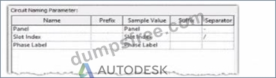
In electrical settings. Phase Labels have not been modified from the default "A." "B." and "C- The Circuit Number lot a single-pole circuit in the panelboard's first breaker position is----------(Enter the correct value into the field)
Answer:
Explanation:
See the explanation
Explanation:
The answer is P1/1/A
In Autodesk Revit Electrical Design, the Circuit Number for a branch circuit in a panelboard is automatically generated based on the Circuit Naming Scheme specified in the project's Electrical Settings. This naming scheme defines how each circuit is labeled by combining predefined fields such as Panel Name, Slot Index, and Phase Label.
From the exhibit, the Circuit Naming Parameter setup is configured as:
Name
Prefix
Sample Value
Suffix
Separator
Panel
Panel
Panel
-
"-"
Slot Index
Slot Index
Slot Index
-
"/"
Phase Label
Phase Label
Phase Label
-
-
The panelboard properties show that its Circuit Naming method is set to PanelSlotPhase, which means that Revit will generate circuit numbers using the following structure:
[Panel Name] - [Slot Index] / [Phase Label]
From the exhibit:
Panel Name: P1
Slot Index (Breaker Position): 1 (since the question refers to the first breaker position) Phase Label: A (default value for the first phase in a three-phase 120/208V Wye system) Therefore, the Circuit Number for a single-pole circuit in the first breaker slot will be:
✅ P1-1/A
This follows Revit's documented logic for circuit naming. According to the Autodesk Revit MEP User's Guide (Chapter 17 "Electrical Systems"):
"The circuit numbering format is controlled by the Electrical Settings > Circuit Naming template. The default scheme combines panel name, circuit number, and phase label, using the separators defined by the user." Furthermore, the Smithsonian Facilities Revit Template User's Guide confirms:
"In the default electrical configuration, circuit numbers use the format [Panel Name]-[Circuit Number]/[Phase], such as 'P1-1/A' for the first single-pole circuit on phase A." Hence, based on the provided configuration and standard electrical setup, the correct circuit number for the first single-pole breaker position in panelboard P1 is P1-1/A.
References:
Autodesk Revit MEP User's Guide - Chapter 17 "Electrical Systems," pp. 420-427 Smithsonian Facilities Revit Template User's Guide - Section 8.6 "Panel Schedules and Circuit Naming Schemes," p. 90 Autodesk Revit Electrical Design Essentials - "Circuit Naming Rules and Panel Configuration Standards"
NEW QUESTION # 65
Refer to exhibit.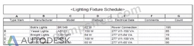
Which two actions were used to create this light fixture schedule? (Select two.)
- A. Deselected Itemize every instance.
- B. Filtered to only show lights that have a type mark value.
- C. Sorted by type mark.
- D. Added both electrical and switch system settings.
- E. Sorted by instance and quantity.
Answer: A,C
Explanation:
In the given Lighting Fixture Schedule, each row represents a lighting fixture type rather than individual instances, and the "Count" column summarizes how many fixtures of that type exist in the project. To achieve this layout in Revit, two specific actions must be performed in the Schedule Properties dialog:
Deselected "Itemize every instance."
The Revit documentation explains:
"Itemize every instance. This option displays all instances of an element in individual rows. If you clear this option, multiple instances collapse to the same row based on the sorting parameter. If you do not specify a sorting parameter, all instances collapse to one row." By deselecting this checkbox, Revit consolidates identical fixture instances of the same type into a single row - exactly as shown in the exhibit, where each "Type Mark" (A, B, C, etc.) appears once with a summarized Count.
Sorted by Type Mark.
On the same Sorting/Grouping tab, Revit allows users to organize the schedule by a specific field:
"On the Sorting/Grouping tab of the Schedule Properties dialog, you can specify sorting options for rows in a schedule... You can sort by any field in a schedule, except Count." In the example, fixtures are sorted alphabetically by their "Type Mark" (A through E). This ensures the grouped and counted results appear in order.
Other options-such as filtering by type mark or adding switch data-do not impact how instances collapse or group within the schedule.
NEW QUESTION # 66
Refer to exhibits.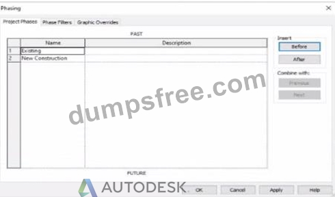
An electrical designer models an existing receptacle on an existing wall that the architect has indicated to be demolished.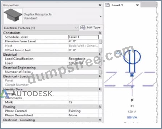
The view is intended to show demolition, and the view's Phase is set to New Construction. How should the designer indicate that the receptacle must also be demolished?
- A. Set the receptacle parameter Phase Demolished to New Construction.
- B. Set the receptacle's type parameter Match Phasing to Host.
- C. Add a Demolition phase, then set the receptacle parameter Phase Demolished to Demolition.
- D. Set the receptacle parameter Phase Demolished to Demolition.
Answer: A
Explanation:
In Autodesk Revit, phasing allows designers to track existing, demolished, and new elements across different project stages. Every model element includes two key phasing parameters:
Phase Created - defines when the element was built or introduced.
Phase Demolished - defines when the element is removed or demolished.
In the provided exhibits:
The project contains two phases: Existing and New Construction.
The receptacle's Phase Created parameter is set to Existing, indicating it belongs to the pre-existing building condition.
The architectural wall hosting the receptacle is to be demolished during New Construction.
When a view's Phase is set to New Construction and its Phase Filter is configured to show demolition, only elements whose Phase Demolished equals New Construction will appear as to be demolished. Therefore, the electrical designer must set the receptacle's Phase Demolished value to New Construction so that it graphically displays as a demolished element in the demolition plan.
As explained in the Autodesk Revit MEP User's Guide - Phasing and Coordination:
"Elements created in one phase and demolished in a subsequent phase must have their 'Phase Demolished' parameter set to that later phase to display properly in demolition views." Thus, to correctly coordinate with the demolition of its host wall, the receptacle must be flagged for demolition during New Construction.
NEW QUESTION # 67
Refer to exhibit.
(The Image is presented in Imperial units: 1 In = 25 mm [Metric units rounded).)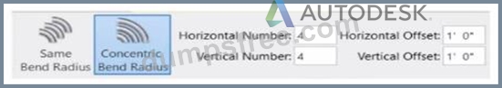
What is the electrical designer trying to do as shown in the exhibit?
- A. Add Cable Tray
- B. Place Parallel Conduits
- C. Place Multiple Pipe
- D. Array Conduit
Answer: B
Explanation:
The exhibit shown in the image is taken directly from the Revit MEP Electrical Systems workspace, specifically from the Parallel Conduits command interface. This dialog box appears when the designer activates the Place Parallel Conduits tool in the Systems tab → Electrical panel → Conduit dropdown → Parallel Conduits.
In this interface, the designer can specify:
Horizontal Number / Offset - defines how many conduits will be created horizontally and their spacing.
Vertical Number / Offset - defines how many conduits will be created vertically and their spacing.
Bend Radius Options:
Same Bend Radius - all conduits use identical bend radii.
Concentric Bend Radius - conduits bend concentrically around a common center point.
According to Autodesk's Revit MEP 2011 User's Guide (Chapter 18, Electrical Systems - Conduit Layout):
"The Parallel Conduits tool allows you to create multiple conduits side-by-side at the same time.
You can specify the number of conduits horizontally and vertically, as well as the offset between them.
You can also define whether bends have the same bend radius or concentric bend radii."
- Revit MEP User's Guide, Electrical Systems, Section: Conduit Layout
This tool is used when electrical designers need to route groups of conduits that run in parallel-such as power and data conduits running between panels or equipment racks.
The Concentric Bend Radius option (as shown in the exhibit) ensures all conduit bends share a common center, which is critical for maintaining uniformity in conduit sweeps and avoiding clashes during coordination.
Therefore:
A . Add Cable Tray - incorrect; the cable tray tool is separate and does not use bend radius options.
C . Array Conduit - incorrect; arraying is a different geometric function not specific to conduit routing.
D . Place Multiple Pipe - incorrect; applies to mechanical piping systems, not electrical conduits.
The display of Concentric Bend Radius, Horizontal Number, Vertical Number, and Offset confirms that the designer is using the Parallel Conduit placement tool.
Verified Reference Extracts from Revit Electrical Design Documentation:
Autodesk Revit MEP User's Guide (2011) - Electrical Systems → Conduit Layout → "Parallel Conduits Tool" description.
Autodesk Revit MEP Training Curriculum - Electrical Module, Exercise 6.3 "Placing Parallel Conduits," which illustrates the same interface for bend radius configuration.
NEW QUESTION # 68
......
The RVT_ELEC_01101 study materials of our company is the study tool which best suits these people who long to pass the exam and get the related certification. So we want to tell you that it is high time for you to buy and use our RVT_ELEC_01101 Study Materials carefully. Now we are glad to introduce the study materials from our company to you in detail in order to let you understanding our study products.
RVT_ELEC_01101 Exam Exercise: https://www.dumpsfree.com/RVT_ELEC_01101-valid-exam.html
- Web-Based Practice Test Autodesk RVT_ELEC_01101 Exam Questions ???? Open ▶ www.verifieddumps.com ◀ and search for { RVT_ELEC_01101 } to download exam materials for free ????RVT_ELEC_01101 Training Questions
- RVT_ELEC_01101 Reliable Exam Questions ???? RVT_ELEC_01101 Reliable Exam Questions ???? RVT_ELEC_01101 Reliable Exam Bootcamp ???? Open ➥ www.pdfvce.com ???? and search for ➠ RVT_ELEC_01101 ???? to download exam materials for free ????Valid RVT_ELEC_01101 Test Review
- 100% Pass Quiz Autodesk - RVT_ELEC_01101 - High-quality Autodesk Certified Professional in Revit for Electrical Design Latest Real Exam ⛰ Open ▛ www.prep4away.com ▟ enter ✔ RVT_ELEC_01101 ️✔️ and obtain a free download ????Latest RVT_ELEC_01101 Exam Bootcamp
- Valid RVT_ELEC_01101 Exam Questions ???? RVT_ELEC_01101 Reliable Exam Bootcamp ???? RVT_ELEC_01101 Reliable Exam Bootcamp ???? Search for ➥ RVT_ELEC_01101 ???? and easily obtain a free download on ➽ www.pdfvce.com ???? ????Valid RVT_ELEC_01101 Test Review
- 100% Pass Quiz Autodesk - RVT_ELEC_01101 - High-quality Autodesk Certified Professional in Revit for Electrical Design Latest Real Exam ???? Search on ✔ www.dumpsquestion.com ️✔️ for ⏩ RVT_ELEC_01101 ⏪ to obtain exam materials for free download ????Trustworthy RVT_ELEC_01101 Pdf
- Hot RVT_ELEC_01101 Latest Real Exam – The Best Exam Exercise for RVT_ELEC_01101 - Efficient Visual RVT_ELEC_01101 Cert Test ???? Download ⮆ RVT_ELEC_01101 ⮄ for free by simply searching on ▛ www.pdfvce.com ▟ ????Reliable RVT_ELEC_01101 Braindumps Book
- RVT_ELEC_01101 Latest Real Exam | Autodesk RVT_ELEC_01101 Exam Exercise: Autodesk Certified Professional in Revit for Electrical Design Pass Certify ???? Download ➥ RVT_ELEC_01101 ???? for free by simply searching on ✔ www.dumpsquestion.com ️✔️ ????RVT_ELEC_01101 Instant Discount
- Latest RVT_ELEC_01101 Exam Pattern ???? Exam RVT_ELEC_01101 Cost ???? Valid RVT_ELEC_01101 Exam Questions ???? Download ⮆ RVT_ELEC_01101 ⮄ for free by simply searching on 「 www.pdfvce.com 」 ????RVT_ELEC_01101 Instant Discount
- Latest RVT_ELEC_01101 Exam Pattern ???? RVT_ELEC_01101 Exam Fees ➕ RVT_ELEC_01101 Reliable Mock Test ???? Copy URL 【 www.troytecdumps.com 】 open and search for “ RVT_ELEC_01101 ” to download for free ????RVT_ELEC_01101 Reliable Exam Bootcamp
- 100% Pass Autodesk - RVT_ELEC_01101 - Perfect Autodesk Certified Professional in Revit for Electrical Design Latest Real Exam ???? Simply search for ( RVT_ELEC_01101 ) for free download on ➤ www.pdfvce.com ⮘ ????RVT_ELEC_01101 Training Questions
- RVT_ELEC_01101 Latest Real Exam | Autodesk RVT_ELEC_01101 Exam Exercise: Autodesk Certified Professional in Revit for Electrical Design Pass Certify ???? Search for ▶ RVT_ELEC_01101 ◀ and easily obtain a free download on ➽ www.testkingpass.com ???? ????RVT_ELEC_01101 Reliable Exam Questions
- bookmarkleader.com, aoifecmhu589410.thebindingwiki.com, jakubfpid247973.nico-wiki.com, georgiahvbt384902.anchor-blog.com, bookmarkspring.com, followbookmarks.com, haarispuyq921065.law-wiki.com, denisxfof916246.wikikali.com, brianlqii630752.blogofchange.com, umarousl664480.wikinewspaper.com, Disposable vapes
DOWNLOAD the newest DumpsFree RVT_ELEC_01101 PDF dumps from Cloud Storage for free: https://drive.google.com/open?id=19wNaJWtuLyUvrDdGyvvd3HX91OLDzc3k
Report this wiki page